Introduction
A propeller in propulsion system can transmit power by converting rotational motion into thrust, based on Bernoulli’s principle. The most common propeller is called the screw propeller, with fixed helical blades rotating around a shaft. The first screw propeller in the world was invented in 1835, by John Ericsson and Francis Pettit Smith. Propellers can be used in marine ships, aircrafts, etc. The basic concepts and priciples in marine propulsion are introduced in this blog.
Geometry
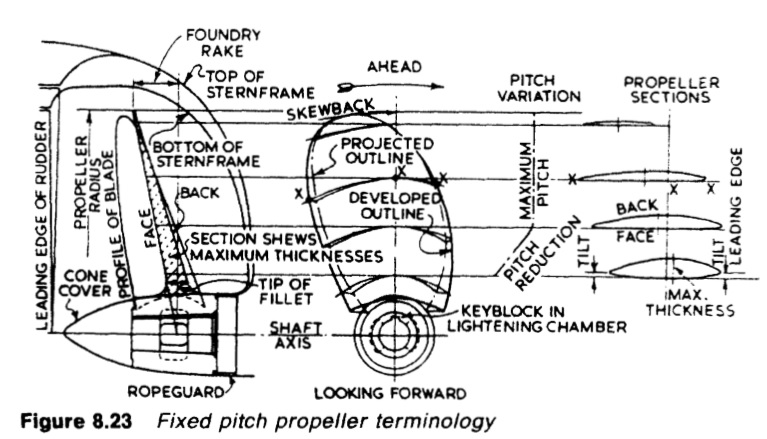
- Hub: The solid center disk that mates with the propeller shaft and to which the blades are attached. A smaller hub can lead to a larger thrust, however there is a tradeoff between size and strength.
- Blade: Twisted fins or foils that protrude from the propeller hub. The shape and the speed at which they are driven dictates the torque a given propeller can deliver. Higher diameter equates to higher efficiency for low speed vehicles (<35kn). To obtain higher torque, the rpm (revolution per minute) should be reduced and the diameter should be increased. In high speed vessels, larger diameters lead to high drag. is used to represent the number of blades.
Here are basic nomenclatures to describe a blade section:

- Leading edge: the point at the front of the airfoil that has the maximum curvature.
- Trailing edge: the point of maximum curvature at the rear of the airfoil.
- Meanline (camber): half distance along a section between the upper and lower surfaces. Quite often the meanline distribution is tabulated forms such as a NACA a=0.8 meanline, where a=0.8 means the meanline can create constant lift of 80% of the chord, then the lift drops linearly to zero at 100%.
- Chord ©: the nose-tail line, connecting the leading edge and trailing edge.
- Camber height (f): the distance between nose-tail line and meanline normal to chord.
- Thickness (t): the section thickness along a line normal to the meanline based on American convention. Thickness measured normal to the chord line is based on British convention.
- Angle of attack (AOA): the angle between a reference line on a body (often the chord line of an airfoil) and the vector representing the relative motion between the body and the fluid through which it is moving. The chord line of the root or the zero lift axis is often chosen as the reference line.
Note that top pressure on the blade section is lower than the bottom pressure. The difference of the pressure leads to the lift force on the blade, thus thrust is generated.
- Face: the pressure face, high-pressure side, faces backwards and pushes the water.
- Back: the suction face, low-pressure side, faces upstream and towards the front of the vessel.
- Leading edge: the side cuts through the fluid.
- Trailing edge: the edge of the downstreams.

- Pitch: the axial distance advanced during one complete rotation of screw is called nominal pitch. The distance the ship is propelled forward in one propeller rotation is actually less than the pitch. The trace of the tip points on the blade is a helix. Pitch ratio is the ratio of pitch to diameter.

- Slip: The difference between the nominal pitch and the actual distance in one retation ().
- Propeller section: A circular arc section cut through the blade at some radius. We can expand it to 2-D foil section.
- Midchord line: the line produced from the midpoint of section nose tail line of each section along a blade.
- Rake: Axial distance from the midchord point at the hub section and the section of interest.
- skew angle: the angle between a radial line going through the hub section midchord point and a radial line through the midchord point of the section of interest AND projected.
Performance
- Speed of advance: the propeller advances through the water at a speed of advance , which delivers a thrust . When the speed of advance is zero, the efficiency is also zero, but the propeller still delivers thrust and absorbs power.
- Thrust power:
- Effective power:
- Wake: In general the water around the stern has acquired a forward motion in the same direction as the ship. This forward-moving water is called wake. The difference between the ship speed V and the speed of advance is the wake speed. The wake fraction is defined as:
- Wake is due to three principal causes:
- The frictional drag of the hull causes a following current towards the stern.
- The streamline flow past the hull causes an increased pressure around the stern. In this region the relative velocity of the water past the hull will be less than the ship’s speed.
- The ship forms a wave pattern on the surface of the water, and the water particles in the crests have a forward velocity due to the orbital motion, while in the troughs the orbital velocity is sternward. This wake will be positive or negative according to whether there is a crest or a trough of the wave in the vicinity of the propeller.
- Thrust deduction: The propeller close to the hull can induce a low pressure on the hull which increases its drag. The trust must be higher to overcome the additional drag. The thrust deduction coefficient is defined as:
where R is the total ship resistance and T is the propeller thrust.
Here are the non-dimensional characterization of the propeller performance.
- Advance coefficient:
- Thrust coefficient:
- Torque coefficient:
- Propeller efficiency:
- Propulsive efficiency:
Because of the wake, the propulsive efficiency for a propeller can be greater than 1.0. It means the propeller can reduce the ship resistance by taking advantage of its wake.

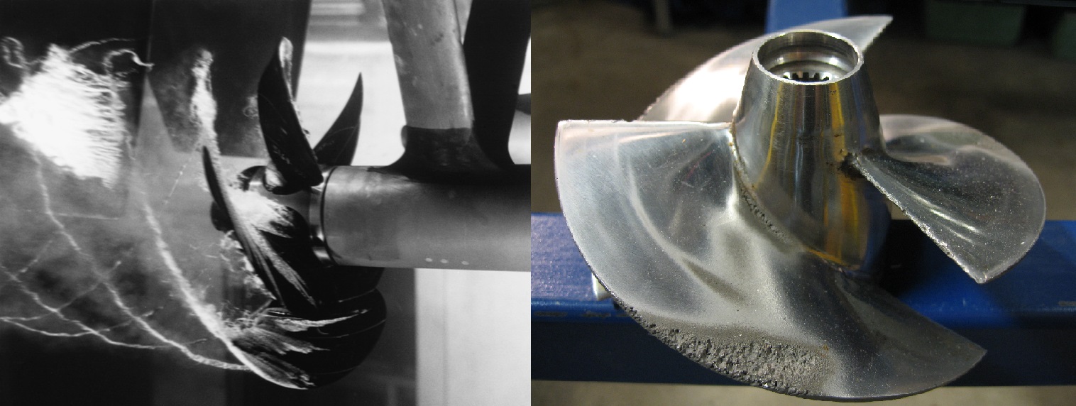
When the local absolute pressure is less than local vapor pressure, cavitation occurs, generally on the suction side. The water can boil in a lower pressure (than atomstpheric pressure) condition even though the temperature is lower than .
- Cavitation number based on inflow velocity:
- Cavitation number based on propeller tip velocity:
Cavitation causes a great deal of noise, damage to components, vibrations, and a loss of efficiency. The pitting caused by the collapse of cavities produces great wear on components. Highly localized collapses of cavities can erode metals over time.

Reference
[1] Wikipedia - Propeller
[2] Wikipedia - Cavitation
[3] MIT 2.016 Hydrodynamics
[4] An introduction to propeller cavitation
[5] Principles of Naval Architecture Volume II: Resistance, Propulsion and Vibration